Canned Preservation Principle (3) - 3-piece Can Body Welding Machine
Published date and time: 2021-01-05, 09:50
Date and time of modification: 2021-07-22, 19:12
Author: Food-Men
The process and principle of food 3-piece can body resistance welding is one of the key parts of can production. This article introduces the welding process and principle of the 3-piece can body welding machine, so as to provide reference for food cans manufacturers.
1. Process of 3-piece Can Body Resistance Welding - Working Process of Welding Machine
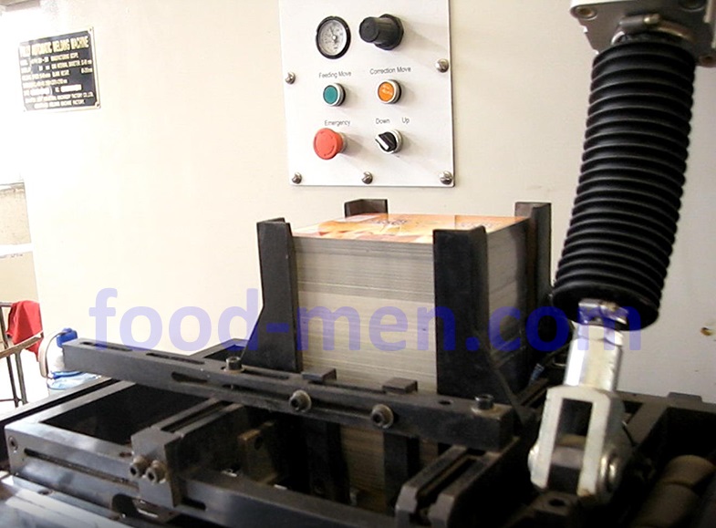
1.1 The tinplate sheets that have been cut are placed in the storage rack, as shown below. There is a push rod under the storage rack, which can push the tinplate to the cylinder forming mechanism one by one.
3-piece can body welding machine Figure 1: Tinplate sheets storage rack
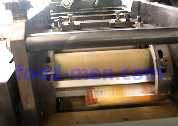
1.2 The cylinder forming mechanism consists of three round rods. The tinplate sheet passes through these three round rods and becomes cylindrical. As shown below:
3-piece can body welding machine Figure 2: Cylinder forming mechanism of tinplate sheet
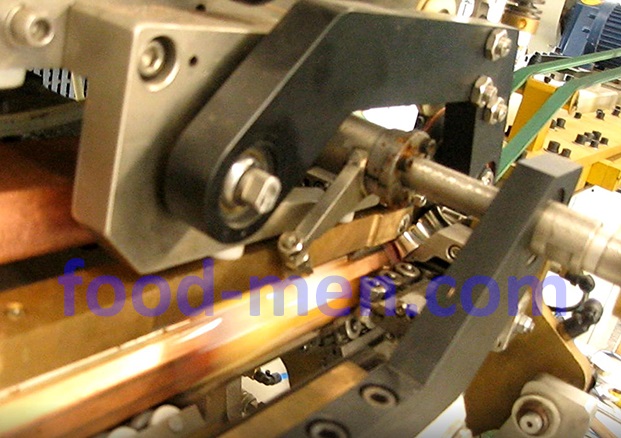
1.3 The curled tinplate sheet (cylinder) is sent to the resistance welding mechanism by a conveyor chain with hooks. There is a swing arm in front of the welding wheel, which is responsible for moving each cylinder into the welding wheel for welding.
3-piece can body welding machine figure 3: Swing arm
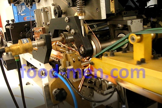
1.4 Resistance welding mechanism is composed of upper welding wheel, lower welding wheel and copper wire. Please see the next section 2 for the principle of resistance welding of the cylinder of the cans .
Can body welding machine figure 4: Instant welding of the longitudinal seam of the 3-piece can body
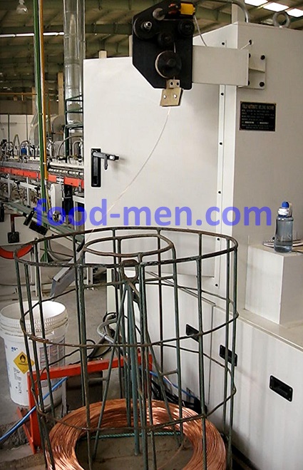
1.5 Copper wire supply mechanism
3-piece can body welding machine figure 5: Copper wire supply mechanism
2. The Principle of 3-piece Can Body Resistance Welding
Schematic diagram of 3-piece can body resistance welding
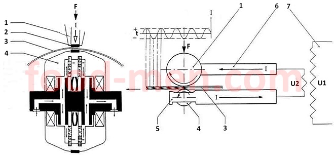
In the diagram:
1 --- Upper welding wheel. Since the welding process generates heat, there is a coolant circulation tube inside the welding wheel to cool the welding wheel.
2 --- Copper wire.
3 --- The 3-piece can body. The two sides of the crimped tinplate sheet (the two sides of longitudinal seam) are in the overlapping state when welding.
4 --- Lower welding wheel. Since the welding process generates heat, there is a coolant circulation tube inside the welding wheel to cool the welding wheel.
5 --- Lower welding arm
6 --- Upper welding arm
7 --- Transformer. U1 is the power supply voltage (380V or 220V); U2 is low voltage, about 126V, high current.
When the can body passes through the upper and lower welding wheels, the welding machine power U2 (alternating current) is turned on, and the current passes through the welding arms, the welding wheels, the copper wire and the overlapped can body sheet. High heat is instantly generated on the overlapped can body sheet. The overlapped can body sheet is welded together at high temperature to form a longitudinal seam of the can body.
According to "Joule's Law", the heat generated when a current passes through a conductor is proportional to the square of the current intensity (I), the conductor resistance (R), and the energizing time (t). Its formula is Q = I2Rt. The time and current that passing through the welding arms, welding wheels, copper wire and overlapped can body sheet are the same. Welding arms, welding wheels, and copper wire have very little resistances, while the overlapped can body sheet has resistances. Therefore, the heat generated by the current is mainly concentrated on the overlapped can body sheet (welds, longitudinal seam).
In order to prevent impurities such as iron and tin on the tinplate from accumulating on the welding wheel, copper wires are wound around the edges of the upper and lower welding wheels. The copper wire moves at the same speed as the welding wheel and tinplate can body. The welding wheel does not touch the can body, only the copper wire contacts the can body. When soldering, the copper wire can promptly remove the iron, tin and other impurities from the can body.
Due to the use of alternating current, and the rapid movement of the can body, short spacing solder joints are formed on the longitudinal seam of the can body. The spacing between solder joints can be expressed by the formula: L = (1000 × v) / (2 × f × 60)
In the formula:
L ---- The distance between the center of two adjacent welding points, mm
v ---- welding speed, m / min
f ---- Current frequency, Hz
In the case where the center distance between two adjacent welding points is constant, the current frequency must be increased to increase the resistance welding speed of the 3-piece can body.
3. Main Factors of Affecting the Quality of Resistance Welding of 3-piece Can Body
(1) Welding current (I): The current is too small, and the welding is not strong. If the current is too large, the weld will become brittle and easy to break. In addition, when the current is too large, the temperature is too high, the metal is over-melted, forming a large molten metal splash point. These metal splash points adhere to the inner surface of the 3-piece can body. Anticorrosive coatings are not easy to cover these metal splash points. In this way, a "steel dew point" is formed, which is easily "intensively corroded" by long-term contact with food.
(2) Welding pressure (F): Too little pressure, increased contact resistance, high welding temperature, but uneven welding. If the pressure is too large, the contact resistance will decrease, the current will increase, and the weld will become wider due to squeezing.
(3) Welding resistance (R): The resistance is related to the thickness, material, overlap width and pressure of the 3-piece can body plate. When the welding resistance increases, the heat generated by the current is concentrated at the weld.
(4) The distance between two adjacent welding points (L): The faster the welding speed, the lower the AC frequency of welding, and the larger L. L is too large, easy to leak.
In addition, if there are impurities in the welding position of the 3-piece can body or the tin layer is too large, it will also affect the quality of the welding.
At present, the method of resistance welding of 3-piece can body has been widely used, and the process is mature, which has replaced electric ferrochrome welding in the can industry.
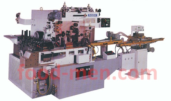
Picture of 3-piece can body resistance welding machine
-------------------------------------------------
Related articles
1. CQM-50 Automatic 3-piece Can Body Welding Machine
2. HJD-35 Automatic 3-piece Big Can Body Welding Machine
3. CQM-35 Automatic Medium 3-piece Can Body Welding Machine
4. GQS-70 Automatic Small 3-piece Can Body Welding Machine
5. WP-10 Longitudinal Weld Seam Inspection Tester for 3-piece Can
6. VG-1A 3-piece Can Weld Seam Inspection Tester System
7. CLT-30 Three Stations 3-piece Cans Leak Tester
8. Anti-corrosion 3-piece Can Body Making Machines Line
9. Milk Powder 3-piece Can Body Making Machines Line
-------------------------------------------------